SHAHIN RABBANI
|
Jacobians are key component in many motion control and analysis techniques. Named after mathematician Carl Gustav Jacob Jacobi (1804-1851), the Jacobian matrix provides an important tool to best describe a linear approximation of a function \(f\) near a point \(x\), given \(f\) is differentiable at that point. We use Jacobian extensively in the computer animation and robotics community, and as a result it is worth providing the reader with the technicalities that help understand its derivation and implementation.
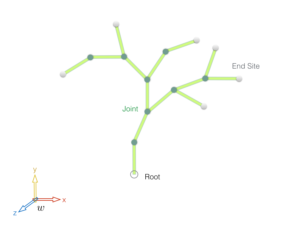
While cite{deLasaPhD2010} explores different approaches to calculate the Jacobian matrix, we focus on two common methods, namely Product of Exponentials and Spatial Axis theorems, with more emphasis on the former, which is also discussed at length by cite{Murray1994}. Finite difference and unit-velocity methods also exist, but they are not efficient because they do not take advantage of the hierarchical tree structure of the multi-link character. Moreover, the finite difference method is an approximation of the Jacobian that is sensitive to the time step as well as the choice of joint angle perturbation, \(\epsilon\). This document mostly covers the technical aspects of computing the Jacobian, and wherever possible, diagrams, algorithms and/or pseudo-codes are given to help the reader with practical hints that make the implementation process easier. If you are less interested in the theoretical foundations of computing the Jacobian, you can skip the derivations in Section ref{subsec:deriv}, but you are encouraged to read the definitions in Section ref{subsec:def}. TODO Guideline To Use This Page: - What sections are suggested to the readers based on their background (color code) - What you find here: Mathematical foundation, intuition, implementation, and a way to unify two types of Jacobian in one code: Euler angle-based (mostly used in kinematics) and rotation matrix-based (mostly used in dynamics). Quaternion lovers can opt for rotation matrix-based Jacobian. - Add multi-block Jacobian system for controlling several end effector positions and rotations simultaneously. - Other good sources: https://homes.cs.washington.edu/~todorov/courses/cseP590/06_JacobianMethods.pdf https://medium.com/unity3danimation/overview-of-jacobian-ik-a33939639ab2 https://mediatum.ub.tum.de/doc/1327698/1327698.pdf For the intuition https://www.khanacademy.org/math/multivariable-calculus/multivariable-derivatives/jacobian/v/the-jacobian-matrix - Table of contents Theory Definitions For a multi-link setup Jacobian relates changes in joint angles, \(\theta\), to positional and orientational changes of some Cartesian point, \(p\), on a link \(i\) \begin{equation} \label{eq:J_diff} ^{i}J(\theta) = \frac{\partial p_i}{\partial \theta}. \end{equation} Jacobian map can be described as the result of differentiating the forward kinematics map \(g: Q \rightarrow SE(3)\). However, this representation is not so easily obtained because \(\frac{\partial g}{\partial \theta}\) is not a natural quantity as \(g\) is a matrix-valued function. Instead, we can use twists in order to achieve a very natural and explicit description of the Jacobian. Rearranging ref{eq:J_diff} and taking time derivative (using the chain rule) we get \begin{equation} \phi_{i} = {^{i}J(\theta)} \dot \theta, \end{equation}where \(\phi_{i} = \dot p_i\) is defined as the twist of the end effector and is written as \begin{equation} \phi_{i} = \begin{bmatrix} v \\ \omega \end{bmatrix} \in \mathbb{R}^6. \end{equation}A twist has a linear velocity \( v \in \mathbb{R}^3 \) and an angular velocity \(\omega \in \mathbb{R}^3\). Twists are the time derivative of a special class of rigid displacements called screw motions. We describe a screw motion of a rigid body from one frame to another through combining the translational and the rotational components of the motion along the same axis. In the derivations given in this document we write twists in the body frame \(b\), i.e. at the origin of each link's frame of reference. We use an adjoint matrix to transform a twist from coordinate frame \(i\) to \(j\) \begin{equation} ^{j}\phi =\,\, ^{j}_{i}Ad \, ^{i}\phi. \end{equation} An adjoint matrix transforming between two different coordinate frames \(i\) to \(j\) is constructed from the blocks of the transformation matrix \(^{j}_{i}E\): \begin{equation} \label{eq:transform} ^{j}_{i}E = \begin{bmatrix} ^{j}_{i}R && ^{j}_{i}p \\ \mathbf{0} && 1 \end{bmatrix} \in \mathbb{R}^{4 \times 4}, \end{equation} corresponding to such change of frame. The adjoint is given by \begin{equation} \label{eq:adj} ^{j}_{i}Ad = \begin{bmatrix} ^{j}_{i}R && ^{j}_{i}\widehat{p}\,^{j}_{i}R \\ \mathbf{0} && ^{j}_{i}R \end{bmatrix} \in \mathbb{R}^{6 \times 6}, \end{equation} where \(^{j}_{i}p\) is the origin of coordinate frame \(i\) in coordinate frame \(j\) and the rotation matrix is \(^{j}_{i}R \in SO(3)\). The cross product (wedge) operator \( \widehat{} \) is in the form of a skew symmetric matrix \begin{equation} \label{eq:cross_hat} \widehat{p} = \begin{bmatrix} 0 & -p_z & p_y \\ p_z & 0 & -p_x\\ -p_y & p_x & 0 \end{bmatrix}. \end{equation} Derivation using the Product of Exponentials formula We use the product of exponentials (PofE) formula (cite{Murray1994}) to derive the Jacobian. An exponential mapping function \(e^{\widehat{\zeta}\theta}: \mathbb{R}^6 \rightarrow SE(3)\) on a twist provides an elegant way of describing a homogenous rigid body motion that facilitates the computation of the Jacobian. Let \begin{equation} \label{eq:g_exp} g(\theta) = e^{\widehat{\zeta_1}\theta_1} \cdots e^{\widehat{\zeta_n}\theta_n} g(0) \end{equation} represent the mapping \(g:Q \rightarrow SE(3)\). We define unit twist, \(\widehat{\zeta} \in se(3)\) in the homogenous coordinates by a \(4 \times 4\) matrix \begin{equation} \widehat{\zeta} = \begin{bmatrix} \widehat \omega && v \\ 0 && 0 \end{bmatrix}. \end{equation} The columns of the body Jacobian is obtained by taking derivative of ref{eq:g_exp} with respect to all joint angles \begin{equation} \label{eq:J_b} ^{b}J(\theta) = \begin{bmatrix} ^{b}\zeta_1 && ^{b}\zeta{^\prime_2} && \cdots && ^{b}\zeta{^\prime_n} \end{bmatrix}. \end{equation} Here, the \(j\)th column of \(J\) is the derivative of the mapping function \(g(\theta)\) with respect to the corresponding joint angle \(\theta_j\), where \(^{b}\zeta{^\prime_j} \in \mathbb{R}^6\) and is computed using the adjoint matrix \begin{equation} \label{eq:J_col} ^{b}\zeta{^\prime_j} = Ad_{(e^{\widehat{\zeta}_j\theta_j} \cdots e^{\widehat{\zeta}_{n}\theta_{n}} g(0)) }^{-1} \zeta_j . \end{equation} The Jacobian \(^{b}J(\theta): \mathbb{R}^n \rightarrow \mathbb{R}^6\) is a configuration-dependent matrix which maps joint velocities to end effector velocities. The \(j\)th column of the body Jacobian \(^{b}J\) is the \(j\)th joint twist, transformed to the end effector link frame. Also, we observe that the special structure of the Jacobian results in relating the velocity of the end effector only to the joints that are present down the transformation chain to the root. For the rest of the joints that do not belong to such chain the corresponding columns simply become zero, signifying no contribution. Note that \(g(0)\) in ref{eq:J_col} appears explicitly. Choosing a spatial coordinate frame such that \(g(0) = I\) simplifies the calculation of \(^{b}J\). Block-wise computation In general, one can consider universal joints with 6 degrees of freedom to express the configuration of any multi-body. This is particularly useful to derive a Jacobian that deals with any rigid body system with arbitrary combination of prismatic and revolute joints. In practice, characters often only have revolute joints with only a translation part for the root. In such case, the redundant adjoint columns can be removed from the Jacobian to match the joint vector \(\theta\). In order to design a routine that constructs the body Jacobian, we replace the columns of \(^{b}J(\theta)\) in Equation ref{eq:J_b} with \(6 \times 6\) adjoint matrix blocks. Particularly, the \(j\)th adjoint transforms the \(j\)th joint velocity, and is obtained from the transformation function given in ref{eq:J_col}. The Jacobian becomes \begin{equation} \label{eq:J_adj_blocks} ^{b}J = \begin{bmatrix} ^{b}_{1} Ad && ^{b}_{2} Ad && \cdots && ^{b}_{m} Ad \end{bmatrix} \in \mathbb{R}^{6 \times m} \end{equation} where \(m\) is the number of the joints. Jacobian frames What we have derived so far is the body Jacobian, i.e. the Jacobian for the point at the origin of the link's coordinate frame. To obtain the Jacobian for an arbitrary location point on a link an additional transformation is needed \begin{equation} ^{p}J(\theta) = ^{p}_{b}Ad ^{b}J(\theta). \end{equation} Because any point attached to a link will have the same angular velocity but not necessarily the same linear velocity, \(^{p}_{b}Ad\) has its rotation set to identity and has only a translational part (for a proof see Appendix B of the PhD thesis by cite{deLasaPhD2010}). We can also transform the body Jacobian to a coordinate frame that is more convenient for the end effector manipulation, such as the world frame. Using an adjoint transforming twists from the body frame \(b\) to the world frame \(w\) gives such Jacobian \begin{equation} ^{w}J(\theta) = ^{w}_{b}Ad ^{b}J(\theta). \end{equation} Jacobian derivative The time derivative of \(^{b}J(\theta)\) is calculated by taking derivative of the adjoint matrices with respect to time. Given \begin{equation} ^{b}_{j}{\dot Ad} \, ^{b}_{j}{Ad}^{-1} = \begin{bmatrix} \widehat{\omega} && \widehat{v} \\ \mathbf{0} && \widehat{\omega} \end{bmatrix}, \end{equation} the derivative of the adjoint is obtained \begin{equation} ^{b}_{j}{\dot Ad}= \begin{bmatrix} \widehat{\omega} && \widehat{v} \\ \mathbf{0} && \widehat{\omega} \end{bmatrix} \begin{bmatrix} R && \widehat{p}\, R \\ \mathbf{0} && R \end{bmatrix} = \begin{bmatrix} \widehat{\omega}R && \widehat{\omega} \, \widehat{p}\,R+\widehat{v}\, R\\ \mathbf{0} && \widehat{\omega} R \end{bmatrix}. \end{equation} The routine to construct \(^{b}\dot J(\theta)\) is the same as \(^{b}J(\theta)\) except we use the adjoint time derivative. Details on designing such routine are discussed in the rest of the document. Implementation In this section we mainly focus on the practical aspects of computing the Jacobian. The goal is to take a step-by-step approach to familiarize the reader with the process of applying the theories explained so far. The Simplest Jacobian For the moment, let us forget about the mathematical derivations and try to use our intuition to build a simple Jacobian. After studying an example, we will then discuss how the computed Jacobian relates to our formulas. Model. Our example workstation model consists of a tree with a floating base (root), 6 end sites (leaves), and 8 spherical joints, that together with the root rotation and translation provide \(8 \times 3 + 6 = 30\) DOF (Degrees Of Freedom). We intentionally choose a different common frame than the root frame, calling it the world frame, to address how to deal with a floating base character where the root linear velocity can also be a part of the solution. This is shown in Figure 1 as the coordinate system with a \(w\) label.
Figure 1. Abstract tree-shape model with a root, joints (branches) and end sites (leaves),
The tree based model is widely used to describe the topology of the human characters, but for the sake of generality, we have chosen a tree shape structure that does not resemble a human skeleton in order to study our methods on an abstract character.
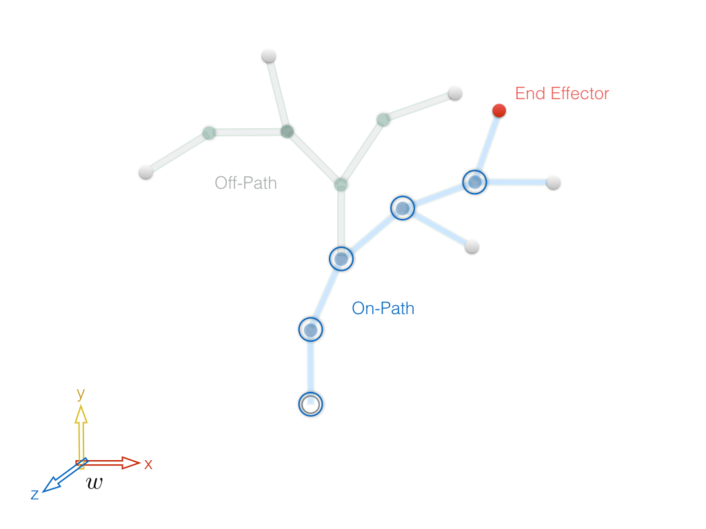
Inverse kinematic problem setup. Figure 2 shows a situation where we would like to gain control over the position of one of the end sites. The selected node is known as the End Effector. Although in our example we picked an end site to be our end effector, it can basically be any of the joints, or some point on the link attached to a joint. Also, we assume that we are only interested in the positional adjustments to such node, while the rotational control will be discussed later on.
Figure 2. Separating the tree into the sub-tree containing the end effector (On-Path) and the one that has no relationship with the end effector (Off-Path).
Identifying the main path. We begin by identifying those joints whose angular changes would directly affect the end effector position. The tree morphology offers the advantage of systematically labeling the joints from the root up to the end effector, leaving out the joints down the other branches. This divides the tree into On-Path and Off-Path subtrees, as shown in Figure 2, where the contributor joints are highlighted by blue rings. Note that a necessary condition for the On-Path joints is that they should belong to the set of the end effector ancestors, leaving out the children of the end effector, if there are any.
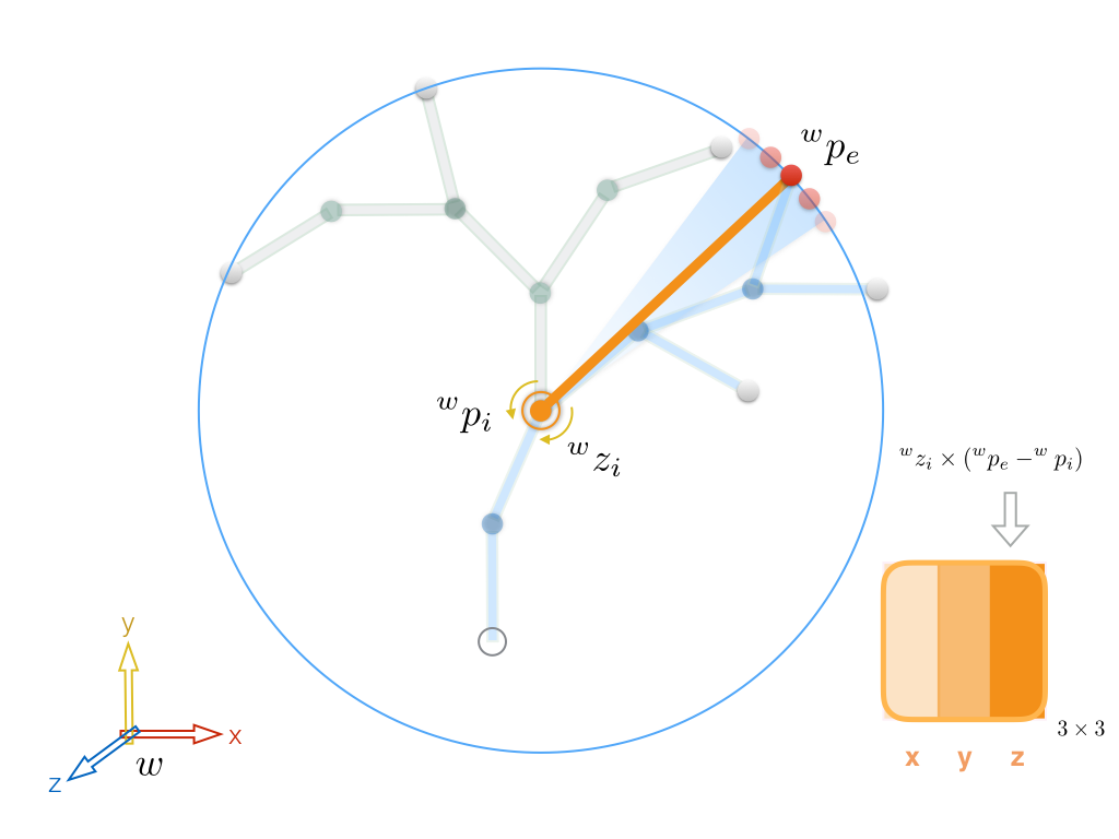
Relating the joint velocities to the end effector velocity. At this stage we compute the relationship between each joint angular velocity and the end effector linear velocity. To that end, we recursively traverse the On-Path joints, starting with the end effector parent and all the way to the root, and compute \(3 \times 3\) contribution blocks that will find their place in the Jacobian matrix based on the index of each joint. For a spherical joint with \(x\), \(y\), and \(z\) rotational axis, such block effectively consists of \(3\) columns, each corresponding to one of these axes. Since we are solving the problem in 3D each column is a \(3 \times 1\) vector, obviously. Note that in case of having other types of joint constraints, this block will likely acquire a different size. For example, replacing spherical joints with hinge joints of \(1\) DOF will result in a block with a single column, reducing its size to \(3 \times 1\). Figure 3 shows an example of computing the contribution of the z axis of one of the On-Path joints to the end effector positional change, or putting it in a more technically correct term, instantaneous linear velocity. Assume that all the other joints in the tree, whether On-Path or Off-Path, are frozen except for the selected \(i\)th joint. Also, since in the given example we are interested in the effect of the joint angular velocity around its z axis, the rotations around the other two axes, x and y, are also frozen. This reduces the problem to a single hinge with an arm connecting its pivot to the end effector. Choosing the world frame as the common frame, we can denote the end effector position in the world coordinates by \(^w p_e\), and its instantaneous linear velocity by \(^w \dot p_e\). Since everything should be done in the same frame, which is typically the world frame in solving an IK problem, we also need to transform the local z axis of the \(i\)th joint to the world frame, denoted by \(^w z_i\). As such transformation would require knowledge about the order of the joint axes Euler angles (\(\overrightarrow{xyz}\) in our example), we skip this part for the moment and will explain shortly after how to compute \(^w z_i\). Assuming we have found \(^w z_i\), and knowing the contributor joint and the end effector positions in the world frame, \(^w p_i\) and \(^w p_e\), we use a cross-product to compute \(^w \dot p_e\) by \begin{equation} \label{eq:zaxis} ^w \dot p_e = {^w z_i} \times ({^w p_e} - {^w p_i}) \end{equation} to be the contribution of the z axis of joint \(i\) to the end effector positional change. The resulting \(3 \times 1\) vector will go to the \(i\)th \(3 \times 3\) contribution block in the Jacobian matrix, locating in either of the 3 vertical locations based on some arbitrary convention set by the user. The other two columns corresponding to the x and y axes will be computed in the similar fashion, except we use \(^w x_i\) and \(^w y_i\) instead of \(^w z_i\) in Equation~\ref{eq:zaxis}.
Figure 3. Using cross product to compute the effects of small angular perturbations to the z axis of a contributor joint \(j_i\) on the end effector position \(p_e\) in the world frame. This problem can be viewed as freezing all other DOFs, reducing the computation to a single hinge that rotates an arm going from the joint position \(^w p_i\) to the end effector position \(^w p_e\).
In general, the contribution matrix block of the \(i\)th contributor joint is
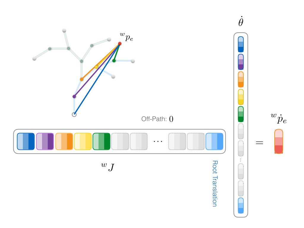
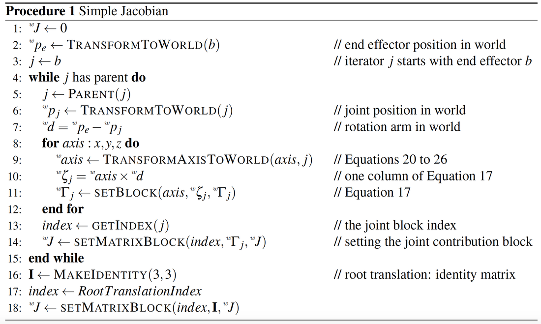
\begin{equation} \label{eq:J_simple_block} ^w \Gamma_i = \begin{bmatrix} ^w\zeta_x && ^w\zeta_y && ^w\zeta_z \end{bmatrix} \end{equation} where \(^w\zeta_{x,y,z}\) are the computed \(^w \dot p_e\) due to x, y and z rotational axes. This is similar to Equation~\ref{eq:J_b} with grouping three columns as one block \(^w \Gamma_i\) pertaining to the \(i\)th joint. However, observe that we use a different notation for the columns in this equation where the superscript \(\prime\) is dropped to highlight the fact that these are not exactly the same twist vectors as in Equation~\ref{eq:J_b}. Transforming a single joint axis. What we just described assumed that we already know how to properly take care of transforming a single rotational joint axis from a local frame to the world frame. In practice, the transformation matrix should be adjusted such that its rotational components respect the Euler angles order. To understand this point, consider how we do such transformation for the z axis in the above example. \begin{equation} \label{eq:trans_z} ^w z_i = {^w_i\! E} \; {^i z_i} \end{equation} where \(^i z_i = (0, 0, 1)^T\) and \begin{equation} ^w_i\! E = \begin{bmatrix} ^w_i R && ^w_i p \\ \mathbf{0} && 1 \end{bmatrix} \end{equation} is the transformation matrix mapping from the \(i\)th joint frame to the world frame, and \(^w_i\! p\) and \(^w_i\! R\) are the translational and rotational components, respectively. However, the problem with Equation~\ref{eq:trans_z} is the mismatch between the transformation matrix dimension (\(4 \times 4\)) and the joint axis dimension (\(3 \times 1\)). The reason is using homogeneous coosrdinates system for the transformation matrix. To obtain a consistent from, we need to augment the z axis with 0 (because it is a vector, as opposed to augmenting 1 for points): \({^i z_i}^{\prime} = (0, 0, 1, 0)^T\). It is straightforward to show that with everything adjusted to be in homogeneous system we can ignore the translational part of \(^w_i\! E\) and re-write Equation~\ref{eq:trans_z} as \begin{equation} \label{eq:rot_z} ^w z_i = ^w_i\! R \; ^i z_i. \end{equation} To understand why we can let go of the \(4 \times 4\) transformation matrix \(E\) and only work with rotation blocks observe how the augmented \(0\) in any vector to be transformed by a full transformation nullifies the effect of the translational part, \(p\) of \(E\): \begin{equation} E.v = \begin{bmatrix} R && p \\ \mathbf{0} && 1 \end{bmatrix} . \begin{bmatrix} v \\ 0 \end{bmatrix} = R.v + p.0 = R.v \end{equation} Remember the augmented \(0\) is only for vectors. We use augmented \(1\) for points in homogeneous transformations, which means the translational part does indeed affect transforming a point. Simply put: vectors are indifferent to translations; but points are not. And it pretty intuitive. Think about it... no matter how much you translate a vector, it still has the same length and points towards the same direction, so it is invariant to translation. The same is not true for transforming points. So we can use this observation to greatly simplify our chain of transformations from now on. This means, more specifically for computing \(^w z_i\), we abandon the augmented \(4 \times 1\) vector \({^i z_i}^{\prime}\) and stick to \(3 \times 1\) vector \(^i z_i\) whose size is consistent with a \(3 \times 3\) rotation matrix \(R\). --> For those who are still struggling to see through this clearly, I am including an expanded (and more redundant) representation of the summary of following equations at the end of this sub-section. Because a careful manipulation of the rotation matrices based on the Euler order only involves adjusting the local rotation matrix from the current joint \(i\) to its parent \(p\), we can write \begin{equation} ^w z_i = ^w_p\! R \;\; ^p_i\! R \;\; ^i z_i = ^w_p\! R \;\; ^p z_i. \end{equation} and then only focus on how \(^p z_i\) is computed. To address the issue of Euler angles order let us go further and break down the local rotation matrix \(^p_i\! R\) in terms of individual rotations around each axis. For a channel order \(\overrightarrow{xyz}\) we get \begin{equation} ^p z_i = (^p_i\! {R_x} \;\; ^p_i\! {R_y} \;\; ^p_i\! {R_z} ) ^i z_i. \end{equation} This means the rotation order \(\overrightarrow{xyz}\) requires us to first rotate around x, then y, then z axis. Since the z axis is the right-most Euler angle, any rotation around x or y would affect the z axis, and hence transforming the z axis will need to include the other two rotations as well. On the other hand, for transforming the y axis, rotations around z will not influence the transformation, and hence becoming identity matrix \begin{equation} ^p y_i = (^p_i\! {R_x} \;\; ^p_i\! {R_y} \;\; \mathbf{I}) ^i y_i = (^p_i\! {R_x} \;\; ^p_i\! {R_y}) ^i y_i. \end{equation} Likewise, for the x axis we have \begin{equation} ^p x_i = (^p_i\! {R_x} \;\; \mathbf{I} \;\; \mathbf{I}) ^i x_i = (^p_i\! {R_x}) ^i x_i \end{equation} For \(^p z_i \) with a different channel order, say \(\overrightarrow{zxy}\), the rotation matrix break-down would become \begin{equation} ^p z_i = (^p_i\! {R_z} \;\; ^p_i\! {R_x} \;\; ^p_i\! {R_y} ) ^i z_i, \end{equation} and following the same approach as above, we would have needed to exclude the x and y rotations to get \begin{equation} \label{eq:rot_z_zxy} ^p z_i = (^p_i\! {R_z} \;\; \mathbf{I} \;\; \mathbf{I} ) ^i z_i = (^p_i\! {R_z}) ^i z_i . \end{equation} In general, one can say computing the local axis rotation is the part that needs most attention. Any mismatch between the Euler angles enforced by the character model and computing the transformation of the joint individual axis is potentially the main cause of failing to compute the Jacobian properly. More redundant but perhaps more code-friendly summary of Euler axis chain transformations. Let's pick some Euler order, like \(\overrightarrow{zxy}\), which is a quite common rotation channel order in bvh files; one of the most widely used file formats to store a skeleton hierarchy and its motion data. --> Remember all 3 transformed axis are augmented by \(0\) in the following equations. Transforming the last axis in the \(\overrightarrow{zxy}\) order, y-axis, to the world: \begin{equation} ^w y_i = {^w_i\! E} \; {^i y_i} = {^w_p\! E} \;\; {^p_i\! E} \; {^i y_i} = {^w_p\! E} \;\; ( \begin{bmatrix} \mathbf{I}_{3 \times 3} && p \\ \mathbf{0} && 1 \end{bmatrix} \begin{bmatrix} R_z && \mathbf{0} \\ \mathbf{0} && 1 \end{bmatrix} \begin{bmatrix} R_x && \mathbf{0} \\ \mathbf{0} && 1 \end{bmatrix} \begin{bmatrix} R_y && \mathbf{0} \\ \mathbf{0} && 1 \end{bmatrix} ) \; {^i y_i} \end{equation} Note how we deconstructed and expanded the transformation of the current joint \(i\)to its parent \(p\) shown by \({^p_i\! E}\), which has 4 matrices: 1 for translation only (the left-most) and 3 for the individual rotations in the same order as \(\overrightarrow{zxy}\). I am dropping frame notations \(i\) and \(p\) from \({^p_i\! E}\) to avoid clutter and keep things readable. Transforming the middle axis in the \(\overrightarrow{zxy}\) order, x-axis, to the world: \begin{equation} ^w x_i = {^w_i\! E} \; {^i x_i} = {^w_p\! E} \;\; {^p_i\! E} \; {^i x_i} = {^w_p\! E} \;\; ( \begin{bmatrix} \mathbf{I}_{3 \times 3} && p \\ \mathbf{0} && 1 \end{bmatrix} \begin{bmatrix} R_z && \mathbf{0} \\ \mathbf{0} && 1 \end{bmatrix} \begin{bmatrix} R_x && \mathbf{0} \\ \mathbf{0} && 1 \end{bmatrix} \begin{bmatrix} \color{red}{\mathbf{I}_{3 \times 3}} && \mathbf{0} \\ \mathbf{0} && 1 \end{bmatrix} ) \; {^i x_i} \end{equation} And finally, transforming the first axis in the \(\overrightarrow{zxy}\) order, z-axis, to the world: \begin{equation} ^w z_i = {^w_i\! E} \; {^i z_i} = {^w_p\! E} \;\; {^p_i\! E} \; {^i z_i} = {^w_p\! E} \;\; ( \begin{bmatrix} \mathbf{I}_{3 \times 3} && p \\ \mathbf{0} && 1 \end{bmatrix} \begin{bmatrix} R_z && \mathbf{0} \\ \mathbf{0} && 1 \end{bmatrix} \begin{bmatrix} \color{red}{\mathbf{I}_{3 \times 3}} && \mathbf{0} \\ \mathbf{0} && 1 \end{bmatrix} \begin{bmatrix} \color{red}{\mathbf{I}_{3 \times 3}} && \mathbf{0} \\ \mathbf{0} && 1 \end{bmatrix} ) \; {^i z_i} \end{equation} You see how popping the identity matrices \(\color{red}{\mathbf{I}_{3 \times 3}}\) in the last two equations make intuitive sense: transforming the z-axis to the world does not depend on rotations around x and y, because it comes first in the Euler order \(\overrightarrow{zxy}\). Similarly, transforming the x axis does not depend on the rotation around the y axis, because the x axis precedes y in the Euler order. Again, the ones with only identity matrix are clearly redundant. I am showing them just for better understanding of how things work for each axis transformation. -> Replace all translation p with d in this document? but figures have p.. better name for parent instead? -> Better link for bvh? -> Include python code snippet. \begin{equation} \Biggl( sdfs \Biggr) \end{equation} \begin{equation} \bigl( eeew \bigr) \end{equation} \begin{equation} \big( 3333 \big) \end{equation} \begin{equation} \left(dsdf \right) \end{equation} Putting everything together. At his point we have addressed everything regarding computing a Jacobian block matrix for a contributor joint. Procedure 1 summarizes the routine to build the Jacobian. Figure 4 uses a color code to demonstrate how the On-Path joints are traversed and how each \(^w \Gamma\) block is put in the appropriate place in \(J\), matching the joint angles order in \(\dot \theta\). For a specific color code, there are 3 different shades for each axis. The grey blocks indicate zero matrices for the Off-Path joints. As we are dealing with a floating base root, we also need to include the contribution of each of the root translational components in both \(J\) and \(\dot \theta\). We can choose any part of the Jacobian to place a \(3 \times 3\) root translation contribution (shown by light blue) as long as \(\dot \theta\) follows the same order. Conventionally this block is either placed in the left-most or the right-most position of \(J\). Each column of this block matrix is basically a unit vector because of the one-to-one correspondence between a unit change along each root translational component and the unit positional change for the end effector (for instance we insert \((1, 0, 0)^T\) for the x axis column in the allocated Jacobian root block).
Figure 4. Inverse kinematics problem setup with only revolute joints and only positional control over the end effector. Jacobian \(J\) and the end effector linear velocity \(^w \dot p_e\) are computed in the world frame \(w\). Blocks are \(^w \Gamma_i\) from Equation~\ref{eq:J_simple_block}. The color code visualizes the correspondence between the joint blocks and the joint angles.
Generic Jacobian
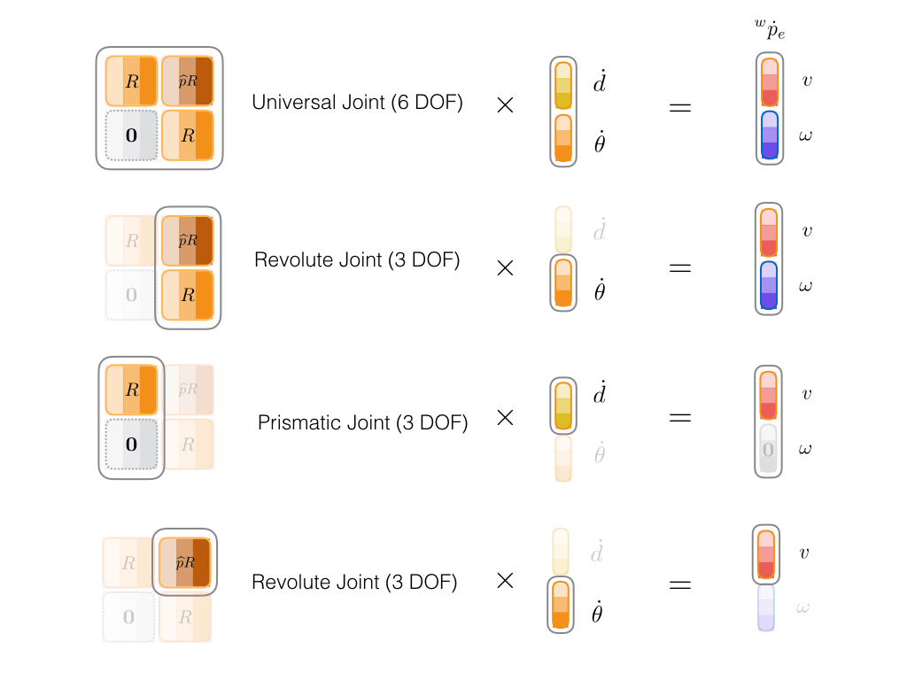
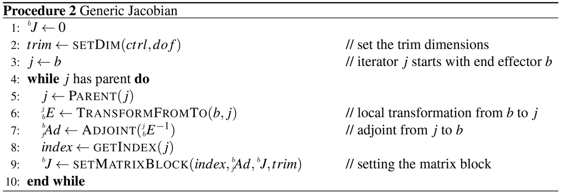
By far you have learnt how to assemble a basic Jacobian with only revolute joints and only positional control over the end effector. In general, we might be dealing with a system with a mixture of prismatic and revolute joints, as well as requiring to gain control over both orientation and the position of the end effector. The cross product method explained above, although simple to implement and accurate, can not be generalized in a simple manner to address more general problems. Also, this method does not help with other rotational representations, such as quaternions and rotation matrices. To achieve a more generic Jacobian we need to go back to Equation~\ref{eq:J_adj_blocks}. In what follows we will examine how to compute such generic Jacobian, and we will see how the cross-product method is just a special case of this generic technique. The generic Jacobian we are going to build consists of \(6 \times 6\) adjoint blocks that are either inserted in the Jacobian as a whole or re-adjusted before insertion based on the joint types and the sort of end effector velocity we want to control. This is shown in Figure 5. As introduced in Equation~\ref{eq:adj}, an adjoint block is in charge of mapping spatial velocity quantities, known as twists, without engaging us in the cumbersome details, like the cross-product method explained before. Assembling the adjoints. An adjoint contains four \(3 \times 3\) sub-blocks: two rotations, one rotated cross product, and one zero block. To compute an adjoint mapping twists from frame \(a\) to frame \(b\) (\(^b_a Ad\)), we first compute the transformation matrix with the same mapping (\(^b_a E\)), then extract the rotational and translational components from \(^b_a E\) to build \(^b_a Ad\). While it is straightforward to copy the rotational components from \(^b_a E\) to \(^b_a Ad\), the rotated cross-product block should be computed by first forming \(\widehat p\) from Equation~\ref{eq:cross_hat} and then multiplying it by the rotation matrix to get \(\widehat p R\). Adjoints are suitable for computing \(J\). Since adjoints transform twists, we can consider transforming joint velocities (\(\zeta\)), to end effector velocities (\(\phi\)), each with one or both of the linear and angular components. As shown in Figure 5, we can arbitrarily add or remove joint linear or angular velocities, denoted by \(\dot d\) and \(\dot \theta\), as well as including or excluding control over the end effector linear or angular velocity, shown by \(v\) and \(\omega\) respectively, to achieve a wide verity of arrangements in our problem setup. Note how we trim the adjoints in the diagram to match the actuation and control dimensions in different example scenarios. The trimmed sub-blocks, or the complete adjoint matrix in the full control scenario shown on top, will be inserted in the Jacobian matrix without any further adjustments. This provides a nice and generic routine with minimal ad-hoc design decisions. The procedure is given in Procedure 2. The given procedure iterates through all joints in the hierarchy that affects a link of interest computing the relevant body adjoints. Those joints with no contribution to the desired link velocity are considered frozen. This means the corresponding adjoint blocks in the Jacobian are zero.
Figure 5. Several scenarios for adjoint block extraction. First row: full adjoint for a universal joint and full control over the end effector linear and angular velocities. Second row: only revolute joint but still full velocity control over the end effector. Third row: only prismatic joint and again full end effector velocity control. Pay attention to \(\omega\) that despite being included in control is forced to be 0 by the setup. This makes sense as a prismatic joint can not affect the angular velocity of the end effector. Last row: a very common setup with only a revolute joint and positional control over the end effector.
You can compare this algorithm to Procedure 1 where you probably find the new method easier to implement. Note the left superscripts in both algorithms. Procedure 1 uses \(w\), world frame, and Procedure 2 uses \(b\), body frame. Also, pay attention to the case of computing the root block, where we need to make sure \(trim\) variable always includes the root translation.
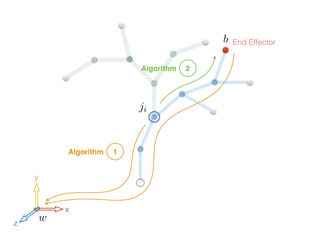
Body frame instead of world frame. In Section~\ref{subsec:deriv} we used PofE to derive a Jacobian based on mapping twists. However, we did not mention why we use the body frame instead of the world frame to be our common coordinates system. While in general the choice of the common frame does not affect the computed Jacobian accuracy (except for very small numerical errors that are safe to be ignored), it might determine if we compute \(J\) in an efficient manner. Adjoints by nature are computed from local transformations between two joints, without the need to first map all the quantities to a more general frame, like the world frame. As Figure 6 shows, when using Procedure 1 we need multiple passes (at least two) to transform our matrices to the world frame, while we only need 1, often shorter, pass in Procedure 2 to map our quantities to the body frame. While in both cases we can take advantage of the recursive structure of the tree to reuse the results of the previous steps, less and shorter passes give intrinsic performance improvement to our code.
Figure 6. Comparing the passes for the two algorithms.
Relationship to the cross-product method. You might have noticed the last row of Figure 5 resembles what we did for creating the simple Jacobian. It involves a cross product and only deals with revolute joints and the end effector linear velocity. This is not a coincidence. In fact, we can show the method we used was a special case of the PofE method.
Recall that a column of the body Jacobian formula in Equation~\ref{eq:J_b} was given as \begin{equation} \label{eq:J_col_recall} ^{b}\zeta{^\prime_j} = Ad_{(e^{\widehat{\zeta}_j\theta_j} \cdots e^{\widehat{\zeta}_{n}\theta_{n}} g(0)) }^{-1} \zeta_j \end{equation} which means an adjoint transforming the \(j\)th twist \(\zeta_j\) to the body frame \(b\). Take note that one should not confuse the \(j\)th axis in this equation with the \(j\)th joint in the algorithm discussed earlier. To clarify this, we can rewrite Equation~\ref{eq:J_col_recall} for, say, the z axis of the \(j\)th contributor joint, while using a more familiar adjoint notation that we just introduced \begin{equation} \label{eq:J_col_jz} ^{b}\zeta{^\prime_{j_z}} = {^{j_z}_{b}Ad^{-1}} \zeta_{j_z} . \end{equation} Here, \(\zeta_{j_z}\) means the twist due to the z axis of the joint \(j\), and \({^{j_z}_{b}Ad^{-1}}\) is the inverse of an adjoint transforming the body frame \(b\) to the z axis of the joint \(j\) frame, shown by \(j_z\). Applying additional transformation to Equation~\ref{eq:J_col_jz} we get the contribution twist in the world frame \begin{equation} \label{eq:J_col_jz_w} ^{w}\zeta_{j_z} = ^{w}_{b}Ad (^{j_z}_{b}Ad^{-1} \zeta_{j_z}) = {^{w}_{j_z}Ad} \;\zeta_{j_z}. \end{equation} We took liberty to drop \(\prime\) of the left hand side twist because it is now a different vector. End effector contribution twist \(^w\zeta_{j_z}\) is the same as the third column of the contribution block we computed for the simple Jacobian method in Equation~\ref{eq:J_simple_block}. The other two columns for x and y are obtained the same way. This shows how the cross product method can be derived using the same technique as PofE. However, the key observation here is computing \({^{w}_{j_z}Ad}\), which is slightly different from \({^w_j Ad}\). While the latter does not take any Euler angles order into account and is directly achieved from \(^{w}_{j}E\), the former assumes different transformation matrices when mapping from x, y or z rotational axis, due to the existence of some Euler angles order. Although the generic Jacobian provides many advantages, and being particularly useful for dealing with joint constraints in quaternion or matrix forms, it is somewhat not very straightforward how to use it with Euler angles. In the above discussion if we had \({^{w}_{j_x}Ad}\), \({^{w}_{j_y}Ad}\) and \({^{w}_{j_z}Ad}\) we could have easily solved this problem. But what does it mean to compute a Jacobian from adjoints for a joint axis respecting a certain Euler order? What follows in the next section proposes a comprehensive solution to generalize our method even more so that the Jacobian can be built for any rotational representation. Summary. Advantages over the cross-product method:
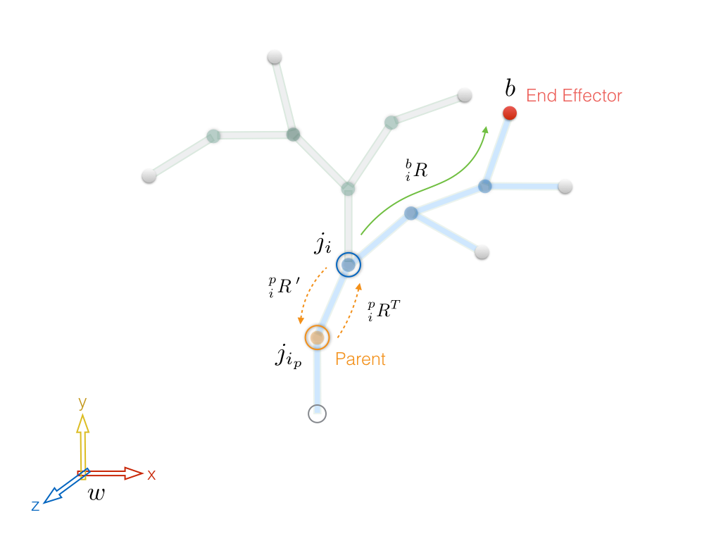
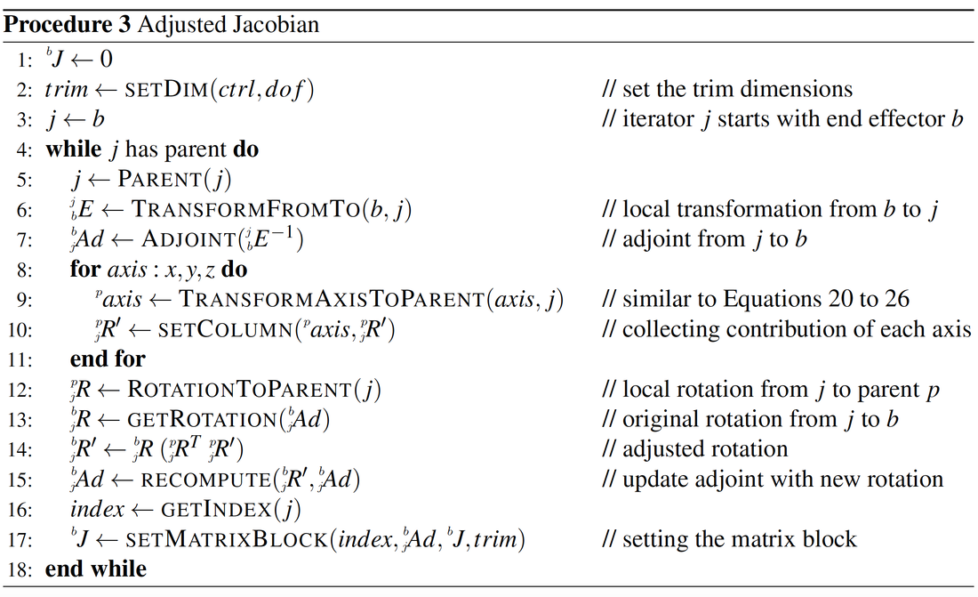
Adjusted Method: Combining Spatial Axis and PofE Jacobian The aim of this section is to add a few lines to Procedure 2 such that the PofE method can also address the Euler angle representation. Particularly, we add additional steps between lines 7 and 8 of Procedure 2 to implement the modifications. The presented approach is inspired by, but differs from, the Spatial Axis method discussed by~\cite{Feather08} as well as~\cite{deLasaPhD2010}. In the computation of the generic Jacobian, we used to focus on the local path between joint \(j_i\) and end effector \(b\), constructing the adjoint operator from the corresponding transformation. To account for the contribution of a single rotational axis of \(j_i\), we take an extra step to study the effects of axial changes of \(j_i\) in its parent frame \(j_{i_p}\). Similar to what we explained for transforming a single joint axis in Section~\ref{subsec:simple_J} (Equations~\ref{eq:rot_z} to~\ref{eq:rot_z_zxy}) we compute single axis transformations for each of the joint x, y and z axes in the parent frame, denoted by \(^p x_i\), \(^p y_i\) and \(^p z_i\). We then define local contribution rotation matrix by combining these vectors to be its columns \begin{equation} ^p_i R^{\prime} = \begin{bmatrix} ^p x_i && ^p y_i && ^p z_i \end{bmatrix} \end{equation} We use \(\prime\) on the constructed rotation to emphasize its difference from the actual rotation of \(j_i\) in \(j_{i_p}\) frame, shown as \(^p_i R\). Using these two rotations we formulate an adjustment rotation as \begin{equation} ^i_i R^{\; \ast} = {^p_i R^T} \; {^p_i R^{\prime}}. \end{equation} Having computed adjoint \(^b_j Ad\) from line 7 of Procedure 2, we right-multiply its rotational component by \(^i_i R^{\; \ast}\) to get an extended rotation \begin{equation} ^b_i R^{\; \prime} = {^b_i R} \;\; {^i_i R^{\ast}} \end{equation} and use it to update the adjoint. The idea is shown in Figure 7. It goes without saying that although our modification does not affect the translational part of the adjoint, we need to recompute \(\widehat p R\) block of the adjoint with the new rotation. Procedure 3 lists the extra steps between lines 8 and 15. The reader should specifically pay attention to line 9 of this procedure. It is similar to line 9 of Procedure 1, yet we transform individual axes to parent instead of world. Also, this is the only part that depends on the Euler angles order in our algorithm. The nice property of the proposed adjustment is that \(^i_i R^{\ast}\) automatically becomes identity if the Euler angles order would not matter, reducing our algorithm back to its generic form.
Figure 7. Computing the adjustment rotation by taking an extra step to include the parent of the current contributor joint into account.
Solving Inverse Kinematics
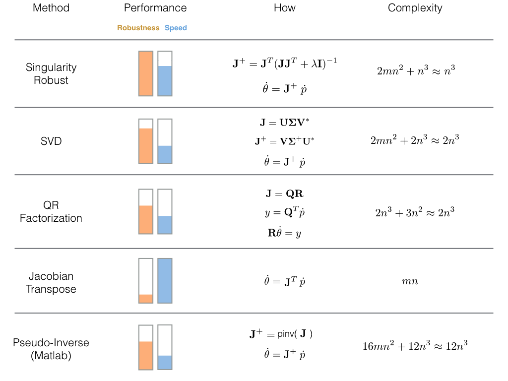
So far we have investigated different methods to compute the Jacobian. In the following parts we briefly give guidance on setting up in inverse kinematic (IK) problem with a few practical hints. Formal Definition In order to derive equations for the inverse kinematics solver we need differential quantities of the desired control handles on the end-effectors with respect to the joints. That is, given a forward kinematics map \(f: Q \rightarrow \mathbb{R}^n\) and a desired configuration \(f_d \in \mathbb{R}^m\), we would like to solve the equation \(f(\theta) = f_d\) for some \(\theta \in Q\), where \(n\) and \(m\) vary based on the type of joints and the controlled features. This is a root finding problem, and it may have multiple solutions, a unique solution, or no solution at all, as discussed by~\cite{Murray1994}. Solutions to this mapping are obtained by iterative solvers that require differentiating the forward kinematic map with respect to the control quantities. This differentiation results in what we have studied as Jacobian. Solvers. Since the Jacobian matrix is not square, we use a pseudo-inverse method to compute the solution \begin{equation} \label{eq:hard_solve} \dot \theta = J{^\dagger} \> \dot p \end{equation} where \(J{^\dagger}\) is the pseudo-inverse of \(J\) and is computed by \begin{equation} \label{eq:psdo_inv} J{^\dagger}= J^T(J \, J^T)^{-1}. \end{equation} Remember all terms in Equation~\ref{eq:hard_solve} must be computed in a common frame (conventionally body or world frame). Equation~\ref{eq:hard_solve} provides a least square solution with minimal norm that remains robust as long as singular configurations are avoided~\big[\cite{Buss04}\big]. We use an iterative method to solve the IK problem because our characters typically have many degrees of freedom (\(25>\)) and the target configuration is defined by a few control quantities which makes it impossible to apply a closed-form IK solver. To help deal with singular configurations, a singularity robust method (SR), also known as damped pseudoinverse, uses a regularization parameter to relax the solution by letting the norm of the solution have some error \begin{equation} \label{eq:psdo_damped} J{^\ast}= J^T{(J \, J^T + \lambda \mathbf{I})}^{-1} \end{equation} where \(J{^\ast}\) is the SR inverse of \(J\), matrix \(\mathbf{I}\) is the identity, and \(\lambda\) is the damping parameter weighting between the error and the norm of the solution. For small values of \(\lambda\) we get smaller errors, but we might as well encounter larger solutions around singular points. Using the SR inverse along with proper tuning of damping \(\lambda\) helps us ease the singularity problem by allowing errors near singular points. Figure~\ref{fig:solvers} summarizes the common methods to solve our linear system. As it is clear from the figure, an SR method makes a very suitable candidate solver both in terms of robustness and speed. Note that the inverse of the term \(J \,J^T + \lambda \mathbf{I}\) can be computed by any method of choice, but since it is a square matrix, we can use LU decomposition for fast computations.
Figure 8. Solvers comparison for a \(n \times m\) Jacobian matrix. Remember \(m\), the number of rows, is the dimension of the end effector position and orientation, and \(n\), the number of columns, is the joints degrees of freedom. For a typical setup with one end effector and multiple joints, we have \( n > m\). You should take note that the given complexities can be improved. For example there exist faster ways than \(O(n^3)\) to invert a matrix, like Optimized CW-like algorithms \(O(n^{2.373})\).
Practical notes
How To Cite This
0 Comments
|
AuthorShahin (Amir H.) Rabbani ArchivesCategories |
Proudly powered by Weebly
 RSS Feed